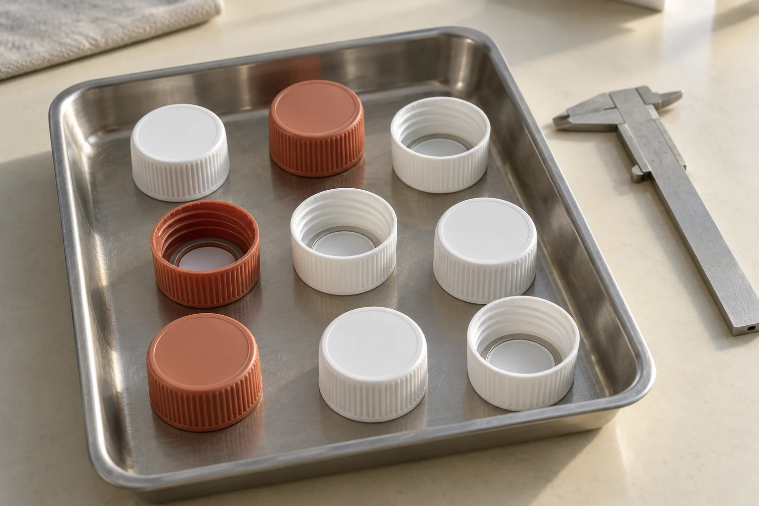
A plastic closure that loses its thread shape during ejection can turn molding output into rejects. This injection molding design guide for plastic closures starts with the mating bottle drawing, then checks the thread-release method, draft and wall geometry before tooling release.

Design an injection-molded plastic closure by resolving sealing geometry and mold release together. A thread intended to strip must permit push-off release while retaining its required bottle engagement; an unscrewing design needs a compatible release mechanism. This guide compares those choices within published supplier guidance, shows how to calculate a simple circular wall, and identifies the evidence needed before approving steel. Use it to prepare a drawing review covering the cap, bottle, resin and ejection sequence. The result should be a documented release decision with open questions assigned to the responsible designer.
| Input or item | Typical value or source | Why it matters |
|---|---|---|
| Bottle/cap interface | Controlled mating drawings | Defines what must still fit after molding and release |
| Thread-release method | Closure maker’s profile guidance | Push-off release and unscrewing impose different design conditions |
| Draft on release faces | Protolabs general guidance: 1° or greater | A review baseline; does not remove a thread undercut |
| Resin and shrinkage allowance | Grade and tooling review required | No universal shrinkage percentage establishes a finished cap dimension |
Choose stripping or unscrewing around the thread profile
Choose stripping only when the thread profile and material support push-off release; assess unscrewing when the thread needs rotational release. The closure maker’s thread-profile explanation describes that tradeoff without giving a numerical stripping limit.
| Release route | Published design condition | Dominant Failure Mode & Prevention |
|---|---|---|
| Stripped thread | Closure pushed off without unscrewing; profile balances mold release and bottle retention; PE and PP are common choices | Thread deformation or lost retention: review release geometry and verify the molded cap’s engagement |
| Unscrewing thread | Mold mechanism unscrews the closure to protect thread integrity; tooling is more complex | Damage from an unsuitable release sequence: document rotational clearance and inspect released threads |
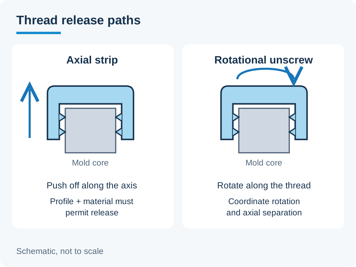
The prevention checks in the table are a proposed design-review plan. They do not establish allowable stripping strain, torque or cycle time. Ask the tool designer to explain the actual release sequence with the selected resin and closure drawing. A statement that the cap uses PP or PE does not settle that review.
Separate production tooling from prototype methods. Protolabs’ molded-thread guide describes hand-loaded internal-thread inserts that are manually unscrewed after molding. That method does not establish the sequence or output of an automated closure mold.
Apply a draft threshold to the right surfaces
Use draft guidance to review faces parallel to the pull direction, while reviewing thread undercuts separately. Protolabs recommends draft of at least 1° for molded threaded parts, consistent wall thickness and avoidance of sharp corners in its “Keeping in Mind Best Practices” section.
Review rule: if a non-thread release face has less than 1° draft, flag it against that published baseline and resolve the exception with the tool designer before release. This is a general supplier recommendation, not a universal minimum for every closure. Applying it to the thread flank would confuse two different geometries.
Mark the pull direction, relevant faces and any intentional exceptions on the drawing review. Record how each exception will be evaluated rather than silently changing a functional sealing surface to meet a generic rule.
Calculate wall thickness in a defined section
Calculate a circular skirt wall from diameters measured in the same plane and about the same centre. For an ideal concentric section:
t = (D_outer − D_inner) / 2
Here, t is radial wall thickness, and both diameters use the same unit. This is geometry, not a cooling-time or shrinkage model.
Worked example — assumed geometry: with D_outer = 30.0 mm and D_inner = 28.4 mm, t = (30.0 − 28.4) / 2 = 0.8 mm. These illustrative dimensions are not a recommended cap wall or a measured production part.
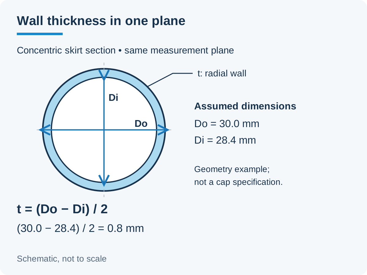
A thread crest, plug, rib or off-centre section changes what the diameters represent. Evaluate those local features separately. A nominal skirt calculation cannot prove local wall uniformity, sealing contact or suitability for stripping. Keep the resin-specific shrinkage allowance as a separate tooling input; the calculation above supplies none.
Account for release losses and maintenance
Compare tooling choices using accepted closures and the work needed to keep them running. The hidden cost can sit in rejected threads, repeated drawing changes or mechanism maintenance rather than the molding step alone. Keep those quantities visible in the compression-versus-injection comparison, which defines a common accepted-output boundary.
| Hidden cost input | What to record | How to include it |
|---|---|---|
| Thread-related rejects | Count and cap mass by defined observation window | Rejected count × mass per cap gives rejected polymer mass |
| Tool intervention | Stopped time, work performed and parts replaced | Track labour and lost accepted output separately |
| Drawing correction | Changed features, review hours and repeat checks | Include the work needed to qualify the revised drawing |
| Downstream rejection | Caps rejected after the agreed finishing and inspection scope | Include these losses in the same accepted-cap denominator |
For a material-only measure, divide consumed polymer mass by accepted cap count over the same reconciled window. A zero accepted count leaves that measure undefined. Do not infer a fixed saving from the mechanism name.
Close the drawing review with functional evidence
Approve the design against the paired drawings and agreed functional checks. Retain the cap revision, bottle-finish revision, resin reference, release sequence and sample identities together. The bottle neck finish compatibility guide explains that drawing-pair discipline.
For the release trial, agree which thread features will be inspected and which assembled-package functions must pass. Record failures by sample identity and cavity where traceable. Leave unresolved geometry, material or acceptance limits open until the responsible parties supply evidence. Use the plastic closure machinery guide to carry those requirements into the wider process comparison.
Methods and sources
Thread-release descriptions follow the closure maker’s public profile page; draft and general threaded-part advice follow Protolabs. Both were accessed October 19, 2026. The wall calculation is elementary geometry using labelled assumed inputs; the cost and release records are editorial recommendations. Neither source supplies a universal closure stripping strain, shrinkage allowance or production cycle.
Updated October 2026.